Consider the Ideal Lowpass Filter Dt Filter Described by
Electrical Engineering questions and answers. I was confused about this a moment ago.
Solved Consider The Ideal Lowpass Filter Dt Filter Described Chegg Com
Xt 3 cos 2π 1500t 2 cos 2π 2200t for t 0 sampled at a rate of 8000 Hz.
. The first step is to obtain the filter specifications or requirements which are determined by the applications. Consider the ideal lowpass filter DT filter described by 4 2π-periodic elsewhere a Find the output for an input signalxfncosーーncos__ n b Find the output for an input signal xn sinc n 4 c Find the output for an input signal xn sinc n 8 cos n 16. And I found out why this is impossible.
It removes high-frequency noise from a digital image and preserves low-frequency components. Consider the ideal lowpass filter DT filter described by 4 -periodic elsewhere a 10 pts Find the output for an input signal x n 2 cos-n 2 b 10 pts Find the output for an input signal xn inc n 2 c 1 0 pts Find the output for an input signal x n sinc n 8 cos n. B 10 pts Repeat part a for the case that the signal x t is sampled at a sampling rate of F s 35 Hz.
The filter specification can be described by discrete-time Fourier transform DTFT. The system is low-pass. MATLAB Ideal Lowpass Filter in Image Processing.
N un 5205 MJRoberts-AlRightsReservedEditedbyDrRobertAkl 45 Discrete-Time Filters Comparison of DT lowpass filter impulse response with RC passive lowpass filter impulse response 5205 MJRoberts-AlRightsReservedEditedbyDrRobertAkl 46 Discrete-Time Filters DT Lowpass. 215c Ideal filters derived from the ideal lowpass filter 234. 2 As the system is a causal.
ILPF passes all the frequencies within a circle of radius from the origin. Answer 1 of 6. How digital filters work in time and in frequency.
The concept of a low-pass filter exists in. Lowpass highpass bandpass and bandstop Unlike continuous-time filters these must have cutoff frequencies. 52 The impulse response of the ideal lowpass filter is easy to calculate.
Sketch the FT of the resulting signal that would be at the output of an ideal DAC like we discussed in class when given these samples. 1 As the impulse response for this ideal low pass filter is a sinc function which means it has non-zero values when t. Sketch the recovered analog signal spectrum if an ideal lowpass filter with a cutoff frequency of 4 kHz is used to filter the sampled signal in order to recover the original signal.
Suppose the requirement is lowpass filter with cutoff a frequency of. Is a positive constant. Electrical Engineering questions and answers.
Consider the ideal lowpass filter DT filter described by 6 0 4 0 4 j e H periodic elsewhere π π π π Ω. Where is the filter from parts a and b and is an ideal low-pass filter with a cutoff frequency of radsample and unity gain in the passband. Consider a system whose input u and output y are related by ut fort a fort a where is a fixed constant.
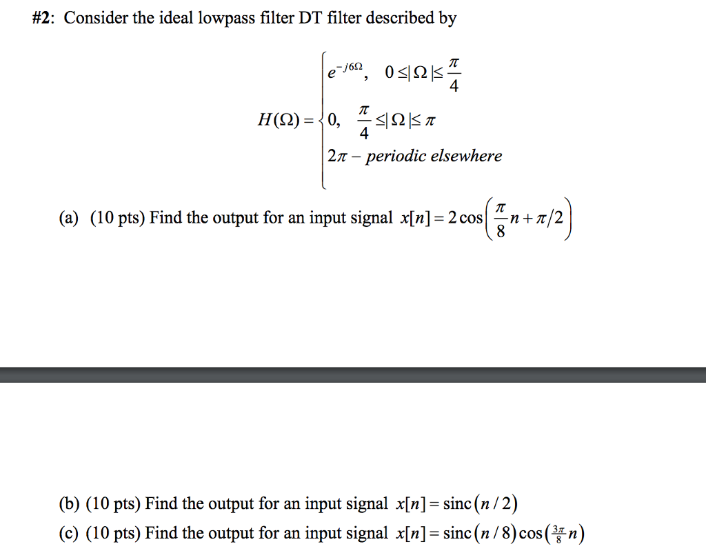
Consider the ideal lowpass filter DT filter described by -j60 e 4 0 4 H. Consider the ideal lowpass filter DT filter described by 2π-periodic elsewhere a 10 pts Find the output for an. Ideal lowpass filter Let us consider in detail the lowpass filter whose amplitude and phase response are given by HLPω p2Bω and HLPω ωtdp2Bω where p2Bω is a rectangle of unit height and width 2B centered at ω 0.
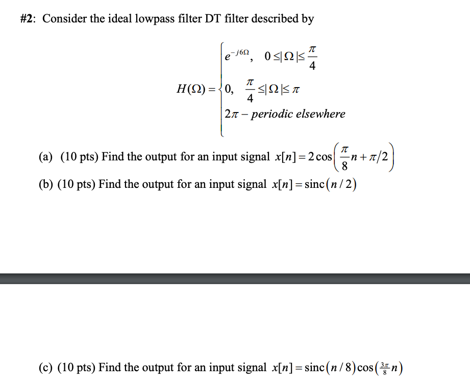
Consider the ideal lowpass filter DT filter described by HOhm e-j6 Ohm 0 lessthanorequalto Ohm lessthanorequalto pi4 0 pi4 lessthanorequalto Ohm lessthanorequalto pi 2pi - periodic elsewhere Find the output for an input signal xn 2cos pi8 n pi2 Find the output for an input signal xn sincn2 c Find the output for an. In the field of Image Processing Ideal Lowpass Filter ILPF is used for image smoothing in the frequency domain. Is the ideal lowpass filter causal.
4 5 ej2F hn 4 5. This is a really good course that has very good exercises. Consider the ideal lowpass filter DT filter described by -j60 e 4 0 4 H 27 - periodic elsewhere a 10 pts Find the output for an input signal xn2 cosnr2 b 10 pts Find the output for an input signal xnsinc n 2 c 10 pts Find the output for an input signal xnsincn8 cos n.
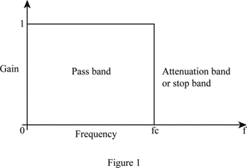
Find the overall frequency response for this system. DT Lowpass Filter HF 1 1. Four commonly used ideal-filter frequency responses are the 1 lowpass filter 2 highpass filter 3 bandpass filter and 4 bandstop filter as shown in Figure 1418.
Ideal Filters 1 Lowpass 1 Highpass 1 Bandpass 1 Bandstop 1 Notch Ω Ω Ω Ω Ωc Ω Ωc Ωc Ωc1 Ωc2 Ωc1 Ωc2 MATLAB can be used to design standard frequency selective filters that meet user-specified requirements These filters include. A low-pass filter is a filter that passes low-frequency signals but attenuates reduces the amplitude of signals with frequencies higher than the cutoff frequencyThe actual amount of attenuation for each frequency varies from filter to filter. Find a simple expression for the frequency response of this filter.
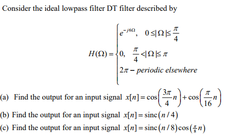
Consider the ideal lowpass filter DT filter described by e-1 051215 69 4 7 H92 0 - Ως π 4 21 - periodic elsewhere a 10 pts Find the output for an input signal xncos 24 cos 16 Зл n b 10 pts Find the output for an input signal xnsincn4 10 pts Find the output for an input signal xnsincn8coskn. If impulse-train sampling is performed on xt which of the following sampling periods would guarantee that xt can be recovered from its sampled version using a appropriate lowpass filter. Given an analog signal.
14432 Denoising Using Digital Filters. A continuous-time signal xt is obtained at the output of an ideal lowpass filter with cut off frequency wc 1000 πππ. 215b The ideal lowpass filter 650.
The impulse response of an ideal lowpass filter is given by sin 20r to gt 20 2wt to for all t where c and to art constants. Sketch the magnitude of. The system is linear and time-invariant.
A linear time-invariant causal continuous time system has a rational transfer function with simple poles at s -2 and s -4 and one simple zero at s -1 A unit step u t is applied at the input of the system. Consider the ideal lowpass filter DT filter described by 4 2π-periodic elsewhere a Find the output for an input signal xncos-ncos-n b Find the output for an input signal xn- sincn 4 c Find the output for an input signal xn sinc n 8 cos 16. Now consider the following digital system.
An ideal lowpass may be characterized by a gain of 1 for all frequencies below some cut-off frequency in Hz and a gain of 0 for all higher frequencies. It is sometimes called a high-cut filter or treble cut filter when used in audio applications. Consider the ideal lowpass filter DT filter described by a Find the output for an input signal xn 2cospi8n pi2 b Find the output for an input signal xn sincn2 c Find the output for an input signal xn sincn8cos3pi8n.
Module 21 Digital Filters. 215a Filter classification in the frequency domain 109. Is it possible to build the filter in the real world.
A T 05 x 10 -3 Sec. To achieve a task of noise reduction. The system is causal.
We have HLPω ejωtdp2Bω so that the impulse response has the form hLPt F1. The simplest filter is an ideal filter with zero phase.
Solved 2 Consider The Ideal Lowpass Filter Dt Filter Chegg Com
Definition Of Ideal Low Pass Filter Chegg Com
Solved Consider The Ideal Lowpass Filter Dt Filter Described Chegg Com
Belum ada Komentar untuk "Consider the Ideal Lowpass Filter Dt Filter Described by"
Posting Komentar